Take a good quality photo of the underside of the board.


Take a good quality photo of the underside of the board.
Thank you. This is what I see on pin 15 of the RAMs. I don't think that's right!
- - - Добавлено - - -
The blue wires are my additions. I also scorched the board a bit when I removed a chip with a heat gun.Сообщение от KTSerg

.jpg?width=450&height=278&fit=bounds&crop=fill)
https://s8.hostingkartinok.com/uploa...654693fdb7.jpg
Marked in yellow where you need to clean.
Marked in red, I can't see.
I cleaned all three areas up with rubbing alcohol until they were shiny, and I verified none of the traces were broken from corrosion. Unfortunately it didn't make any difference.
Are you sure that the bootloader has a built-in RAM test? Never heard of this before...
Still, the bootloader uses the upper RAM for its stack and variables (0xe000-0xffff). Coincidentally, this is also the upper bank of the video frame buffer - the only one used by the bootloader in order to reserve all RAM below 0xe000 for loading programs (hence the pixel "garbage" in the upper right corner of the bootloader grid screen)
So if the corresponding memory chips are corrupted or do not receive proper signals, neither the grid will be visible nor the bootloader will be able to operate normally.
Also, it's strange that you can hear signal coming to the tape input from the speaker. I cannot recall this being the case, as the tape input should go directly to the comparator circuitry.
I would double-check if you are not mistakenly using tape out instead of tape in.
Could be a quirk of the early motherboard revision you have, though.
Последний раз редактировалось x-code; 12.08.2020 в 22:45.
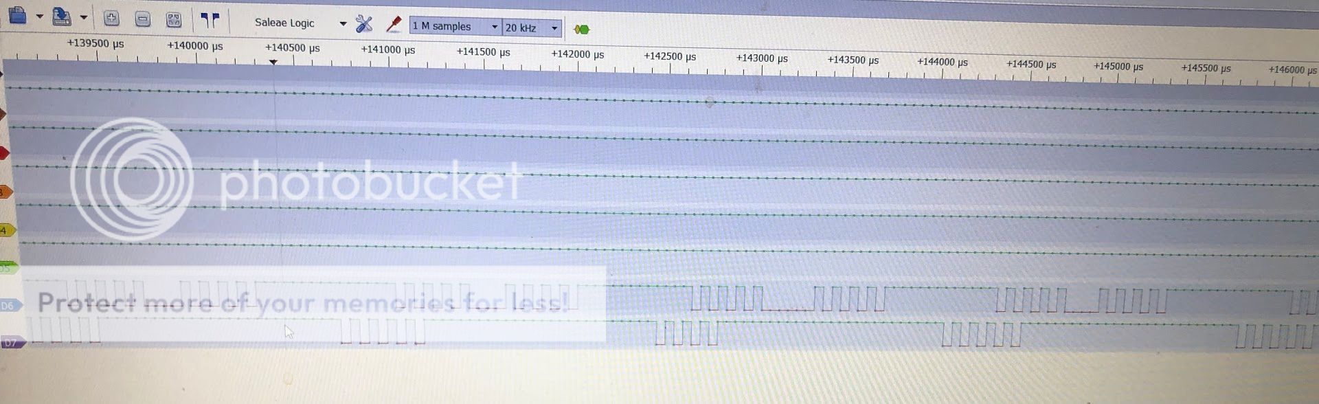
In fact this could be a regeneration cycle (pin 15 is CAS, inverted)
Can you monitor pin 4 (RAS, inverted) along with pin 15?
Pin 4 should be low and pin 15 should be high to trigger regeneration.
But anyways the low frequency "envelope" on your screenshot from the oscilloscope does not look good at all.
Последний раз редактировалось x-code; 12.08.2020 в 22:55.
Maybe I connected to tape out instead of tape in? I used pin 1, with pin 2 for ground.
This computer came with a schematic and a couple tapes. The schematic looks identical to the ones on the vector06c.fdd5-25.net site except the page numbers are different at the bottom.
- - - Добавлено - - -
Channel 6 is pin 4, channel 7 is pin 15, so it seems like it's regenerating.
I have taken a look at the schematics, and tape in is pin 3 of the DIN socket marked as O_O on the backside. Pin 1 is tape out that goes right into the base of the speaker amplifier transistor so this explains why you hear the sound from the speaker.
Отправлено с моего SM-T720 через Tapatalk
Ah, that makes sense. I tried again plugged into pin 3 and it was the same behavior unfortunately.
Perhaps this diagram from a working machine will be of some help:
https://s8.hostingkartinok.com/uploa...ae4d54e9da.jpg
@KTSerg is a much better expert in these timings. Serg, if it's difficult for you to explain in English, write in Russian and I will happily translate.
Последний раз редактировалось x-code; 12.08.2020 в 23:39.
Эту тему просматривают: 1 (пользователей: 0 , гостей: 1)
 Ваши права

 Ответить с цитированием